Search filter
131 results found
Manual fanlight openers
… manual fanlight openers provide fresh air. Thus, natural ventilation is simple and effective, also with closed main windows. Fanlight windows make rooms brighter.
Manual trigger switch
… manual release of hold-open systems
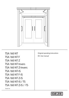
TSA 160 NT user manual
… User manual TSA 160 NT Contents … For the user … Symbols and illustrations Warning notices Warning notices are used in these instructions to warn you of property damage and personal injury. XX Always read and observe these warning notices. XX Observe all measures marked with the warning symbol and warning word . Warning symbol Warning word Meaning Danger to persons. CAUTION Non-compliance can result in minor to medium injuries. Further symbols and illustrations Important information and technical notes are highlighted to explain correct operation. Symbol Meaning means “important note”; information about avoiding property damage means “additional Information” The user's attention should be drawn to important addition information. There is no danger to persons or property, but it is particularly useful to read the additional information carefully. XX … Special cases In certain cases, deviations from the information given in this user manual may occur. Examples: àà special wiring àà special function settings (parameters) àà special software XX Please contact the service technician responsible for further information. … Explanation The side of the door where the hinges from which the door leaf is suspended are located. Usually that side of the door located in the opening direction. The side of the door facing the hinge side. Usually that side of the door located in the direction of closing movement. The active leaf of a double-leaf door. When the door is used, the active leaf must open as the first door leaf and close as the last door leaf. The secondary leaf of a double-leaf door. When the door is used, the passive leaf may not open until the active leaf has left the closing position and must close again as the first door leaf. Push button, switch or movement detector for activating the door drive. The activation device is located within the room enclosed by the door. Activation function in the modes of operation AUTOMATIC and EXIT ONLY 1). The activation device does not have any function in the NIGHT/OFF mode of operation. Push button, switch or movement detector for activating the door drive. The activation device is located outside the room enclosed by the door. Activation function in the AUTOMATIC mode of operation. The activation device does not have any function in the EXIT ONLY 1) and NIGHT/OFF modes of operation. Access control function (for example key switch or card reader) used by authorised persons to activate the door drive. The control function is active in the AUTOMATIC, EXIT ONLY1) and NIGHT/OFF modes of operation. Push button for opening and closing the door. Control function only in the AUTOMATIC and EXIT ONLY modes of operation1). The door is opened automatically when the button is first pressed and closed again automatically when the button is pressed the second time. The function can be activated during commissioning by parameter setting. When the door is pressed manually out of the closing position during an activated closing position inhibition, the door opens automatically as soon as a specific adjustable opening angle is exceeded. Presence detector (e.g. active infrared light switch) for protecting the swinging range of the door in the opening direction. As a rule the sensor is located on the hinge side of the door on the door leaf. Presence detector (for example active infrared light switch) for protecting the swinging range of the door in the closing direction. As a rule the sensor is located on the opposite hinge side of the door leaf. Self-locking switch with which immediate stopping of the door drive can be triggered in case of danger. The door drive remains in its current position until the user unlocks the stop switch again, thus terminating the stop situation. Electrical closing sequence control In normal operation of double-leaf door drives, the closing sequence of the door leaves is controlled by the control units of the door drives, with the passive leaf being closed first. The active leaf remains in the open position until the hold-open time of the passive leaf has expired. Only then does the active leaf begin to close. Integrated closing sequence control (-IS): In the event of a power failure for 2-leaf door systems, the closing sequence is controlled mechanically with TSA 160 NT-F-IS. The door leaves are closed by means of the power storage of the drives, with the active leaf being kept open by the integrated mechanical closing sequence control unit at approximately 30° opening angle before the closing position is reached. When the passive leaf has reached the closing position, it releases the active leaf by means of the mechanical elements of the integrated closing sequence control so that it can also close completely.. The EXIT ONLY mode of operation can only be selected with the optional mechanical programme switch. TSA 160 NT Introduction Term Explanation Electric strike Fail-secure electric strike Available as AC or DC electric strike version. When the door drive is activated, the electric strike is switched on by the control unit of the door drive provided the door is in the closing position. The electric strike remains activated until the door has left the closing position. Fail-safe electric strike DC electric strike version. The electric strike is switched off when the door drive is activated provided the door is in the closing position. The electric strike remains switched off until the door has left the closing position. The bar feedback function is a contact integrated in the door catch that is activated when the door is locked mechanically by the tie bolt of the door lock. It signals to the control unit that the door is locked mechanically and can therefore not be opened by the door drive. In this case the control unit ignores the control commands of all the activation devices. Push button for restarting the drive after the operating voltage has been switched on or after a fire alarm has been terminated. When the push button is pressed, the self-retention integrated in the drive is activated, causing the drive to be activated. When the door is closed in a de-energised state, the door leaf is impeded by the lock latch of the electric strike. To make sure the door can pass the lock latch safely during closing, an integrated limit switch is activated in the drive once a specific opening angle has been reached, reducing the braking strength. The door accelerates and closes into the lock at increased speed. In an energised state, this function is regulated by the drive control unit. Bar feedback Reset Latching function … For the user TSA 160 NT Carefully read and abide by this user manual before commissioning the door. Always observe the following safety instructions: àà Operating, maintenance and repair conditions specified by GEZE must be observed. àà The commissioning, mandatory installation, maintenance and repair work must be performed by experts authorised by GEZE. àà The connection to the mains voltage must be made by a professional electrician. àà No changes may be made to the system without prior agreement from GEZE. àà GEZE shall assume no liability for damage caused by unauthorised changes to the system. àà The owner is responsible for safe operation of the system. àà Have a service technician check the safe operation of the system at regular intervals. àà Should safety devices be misaligned, thus preventing them from fulfilling their intended purpose, further operation is not permissible. The service technician must be informed without delay. àà Make sure that the safety stickers are attached visibly to any glass leaves and are in a legible state. àà Protect the programme switch against unauthorised access. àà Danger of injury by sharp edges on the drive when removing the cover àà Danger of injury by parts hanging down àà This appliance can be used by children aged from … years and above and persons with reduced physical, sensory or mental capabilities or lack of experience and knowledge if they have been given supervision or instruction concerning use of the appliance in a safe way and understand the hazards involved. àà Children shall not play with the appliance. àà Cleaning and user maintenance shall not be made by children without supervision. … 10 *) Door drive Link arm or roller guide rail Smoke switch control unit *) Activation device outside (KA) (optional) Activation device authorised (KB) (optional) Smoke switch *) Activation device inside (KI) (optional) Programme switch (optional) Lockable mechanical program switch (MPS-ST) for releasing the programme switch Stop switch (optional) 11 12 13 14 15 16 17 18 19 20 CLOSE DOOR manual trigger switch *) Electric strike (on site) Door handle with door lock (on site) Inside building Outside building Closing safety sensor (SIS) (optional) Door transmission cable (optional) Opening safety sensor (SIO) (optional) Internal programme switch Reset switch (F-reset) (TSA 160 NT F only) optional, in connection with TSA 160 NT F
(PDF | 411 KB)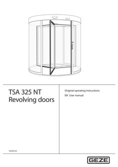
User manual TSA 325 NT revolving doors
… User manual TSA 325 NT Table of contents Supplied system … Burglar-resistant o RC2 Manual revolving door o M Underfloor drive o UFA With automatic positioning device o P Manual night-time closer o NV Automatic revolving door o A Automatic night-time closer o ANV Servo revolving door o S Internal manual night-time closer o INV All-glass o GG Internal automatic night-time closer o IANV Example: TSA 325 NT A3 NV BO = revolving door TSA 325 NT automatic drive with … leaves, with manual nighttime closer and break-out function … About these instructions About these instructions Warning notices Warning notices are used in these instructions to warn you of personal injury and property damage. XX Always read and observe these warning notices. XX Observe all measures marked with the warning symbol and warning word. Warning symbol Warning word Meaning CAUTION Danger to persons. Non-compliance can result in minor to medium injuries. Further symbols and illustrations Important information and technical notes are highlighted to explain correct operation. Symbol Meaning means “important note”; information about avoiding property damage means “additional Information” The user's attention should be drawn to important addition information. There is no danger to persons or property, but it is particularly useful to read the additional information carefully. XX … TSA 325 NT General safety notices Carefully read and abide by this user manual before commissioning the door. Always observe the following safety instructions: XX Make sure that the relevant accident prevention regulations and standard EN 16005 are observed. XX Observe any relevant additional national and European directives. XX Operating, maintenance and repair conditions specified by GEZE must be observed. àà Maintenance and repair work may only be performed by properly trained personnel authorised by GEZE. The protective conductor must be connected. àà Only trained, GEZE-authorised personnel may open the cover. àà GEZE shall assume no liability for damage caused by unauthorised changes to the system. àà The door system is solely suitable for use in entrances and interior areas of pedestrian traffic in commercial plants and public areas. àà The owner is responsible for safe operation of the system. If safety equipment is misaligned, causing it to no longer fulfil its intended purpose, further operation is no longer permissible. Inform the service technician immediately. àà In accordance with Machine Directive 2006/42/EC and EN 16005, a safety analysis must be performed and the door system identified in accordance with CE Identification Directive 93/68/EEC before the door system is commissioned. àà If there are any glass breakages (ceiling, leaf or drum wall), put the door out of use immediately and use suitable measures to prevent anyone entering the area (e.g. barrier tape). Notify a service technician. àà The door may stop unexpectedly if a safety function is triggered. It is possible that persons may walk into a stopped door leaf and hit it. àà If possible, the glass on the drum wall and side-hung leaf must be labelled at eye level through appropriate measures, to prevent persons from running into it. àà When switching over to night mode, the operator must ensure that no persons have been trapped in the door system. … mm. àà To ensure user safety, sufficient ambient lighting must be available. àà The setting for the revolving speed of the door system must be adjusted to the expected users of the system. It may be necessary to reduce the speed. àà Persons may stand in front of and inside the door system only to pass from one area to another area. àà In general, no one may stand on the roof of the door system. … Intended use The door system is solely suitable for use in entrances and interior areas of pedestrian traffic in commercial plants and public areas. Make sure the door system is used for this purpose during operation. Heed the following points when using the door system: XX Make sure that the electrically powered turnstile is not accelerated manually. XX Adapt the walking speed of the door system. XX Make sure that the opening is large enough for entering and leaving the door system. XX Do not stand still in the door system or change directions. XX Ensure sufficient distance to the drum wall and the side-hung casement. XX Do not stand still in the direct vicinity of the door entrance or exit. XX Do not enter the door carrying bulky objects or pushing a trolley (e.g. shopping trolley). XX Make sure children are always accompanied when they enter the door system. XX Keep children at play away from the door system. XX Keep animals on a short lead or carry them. The door system must be used for the intended purpose so that the revolving door safety sensors do not unexpectedly slow or stop the door system in operation. In certain conditions, changing weather conditions (wind, snow, rain, bright sunshine) can cause brief interruptions or standstill of the door system. This is not a fault, rather it is to guarantee user safety. … TSA 325 NT Explanation Rubber strip on the right post of the door system. When the rubber strip is pressed, this triggers a stop of the door system. After the rubber strip is released, the drive restarts independently after a set pause time. Rubber strip on the bottom leaf profile. When the rubber strip is pressed, this triggers a stop of the door system. After the rubber strip is released, the drive restarts independently after a set pause time. Rubber strip on the exterior vertical door leaf profile. When the rubber strip is pressed, this triggers a stop of the door system. After the rubber strip is released, the drive restarts independently after a set pause time. Optional; sticker on the door leaf when using doors with break out door fittings in emergency exit systems. Optional; use with revolving doors with a diameter over 3,000 mm. The safety sensor reduces the revolving speed when the door leaf approaches a person or triggers a stop of the door leaf. GEZE door variants Door variant Manual doors Manual doors with speed limiter Manual doors with automatic positioning device Servo doors Fully automatic revolving doors … Special feature Doors without safety function, exclusively for manual use The max. speed of the revolving door is limited by a safety mechanism in the door. Once it has been passed, the manual door is moved motor-driven to its initial/end position at very low speed. The programme switch must be set to the manual mode of operation. Increased comfort compared with a manual door thanks to automatic starting of the turnstile with radar movement detector. In order to reach walking speed, the turnstile can be overridden by hand. After the door has been passed, it revolves slowly to the final position. The speeds are limited. The programme switch must be set to the manual mode of operation. Activation via movement detector. Electromechanical drive with two pre-adjustable speeds. The revolving movement starts automatically. Special feature The drum walls do not have a frame at the top or bottom and the door has a glass roof. The drum walls have a frame and the door has a glass roof. The side-hung casements can be broken out in any position by pressing the outer edge of the leaf. When a leaf is broken out, the drive is switched off immediately. The door leaves can be engaged again by hand. Then the door continues revolving until it reaches its end position. Burglar-resistant fitting system tested in accordance with DIN EN 1627 1630. Special version of the night-time closer, drum walls and roof. TSA 325 NT … What does the door do? The door begins to revolve. The door slows down to a standstill if necessary. As soon as the passing leaf comes nearer than the preset danger distance, the door slows down to a standstill. The door slows down to a standstill. The door slows down to a standstill. Additional door functions In addition to the keypad programme switch, various additional functions control the door manually via switches or push buttons. Which switch/push button? Emergency stop switch Key push button of the keypad programme switch Contact sensor “Authorised” (e.g. outside key push button) Activation button Push pad Key switch for night-time closer … 99). The arrow keys are used for entry. The factory setting is 00 (released). Operating status Automatic TPS-KDT Explanatory notes All the connected pulse generators are active in the “Automatic” operating mode. Revolving speed and time delay can be set. When activated by a movement detector the door accelerates to the set automatic speed, continues to revolve at this speed and stops in the target position after a preset number of sectors. The following special functions are possible in the “Automatic” operating mode: Summer operation The turnstile stands still without activation. When activated for the first time, the revolving door accelerates to automatic speed. After that the revolving door revolves at the automatic speed for a number of sectors that can be set and then slows to the run-on speed. The revolving door revolves at the slow speed for a set time delay and then stops in the next target position. This operating mode is particularly suitable for creating an welcoming atmosphere. If the time delay is set to endless, the revolving door revolves permanently. Winter operation The turnstile stands still without activation. When activated, the revolving door accelerates to the automatic speed. After that the revolving door revolves at the automatic speed for a number of sectors that can be set and then stops in the target position. In “Automatic” operating mode, alteration between summer and winter operation can be affected by simultaneously pressing the buttons and . If winter operation is selected, the LED “Winter” is illuminated in the TPS-KDT. Exit only Manual Night mode … Activation of push pad (optional) A switch with a wheelchair symbol is located on the door. When this switch is activated, the door brakes and revolves at the set disabled access speed. This speed is specified for the set number of sectors. In the “exit only” operating mode the door is only activated via the internal movement detector, then revolves for a set number of sectors at automatic speed and then stops again in the target position. The turnstile can be rotated freely in manual operation. If no further functions are set, the “Manual” operating mode is identical with the “Off” operating mode. The following options can be set: àà An automatic positioning device returns the door to the target position at slow speed after passing has been completed. àà Safety devices can be activated. àà The speed limiter can be activated. àà Prescribed mode of operation for revolving doors with automatic positioning device and servo revolving doors. The following options for locking can be built into the system in order to lock it in the “Night” operating mode: No locking If the revolving door does not have a locking function, it can be revolved manually in the “Night” operating mode. TSA 325 NT Operating status Night mode Operation TPS-KDT Explanatory notes Manual locking A rod locking can be used as a manual locking element. A contact used to monitor the locking operating mode is installed. Unlock Lock XX Disengage lock. XX Disengage lock. XX Unlock leaf. XX Lock leaf. XX Engage lock. XX Engage lock. The leaf locking mechanism may also function as mirror-inverted for the all-glass version (AG). To lock the door manually: XX Select the “Night” operating mode at the keypad programme switch. The Night LED flashes on the TPS-KDT. The door revolves automatically to the locking position. XX Lock the locking device manually. The Night LED switches to continuous light. Unlocking the door manually: XX Unlock the locking device manually. The Night LED of the TPS-KDT switches to flashing. XX Set the desired operating mode on the TPS-KDT. The LED indicates the operating mode. Locking device with disc brake A disc brake can be used to lock the revolving door. When the power supply is interrupted, the brake is opened. The revolving door can then be revolved manually. It is not suitable for a revolving door with break-out function. Locking the door: XX Select the “Night” operating mode on the TPS-KDT. The Night LED flashes on the TPS-KDT. The door revolves automatically to the locking position. The disc brake is activated. The Night LED switches to continuous light. Unlocking the door: XX Select the desired operating mode on the TPS-KDT. The disc brake is released. The new operating mode is active and is displayed on the TPS-KDT. … Operation Operating status Night mode TSA 325 NT TPS-KDT Explanatory notes Electromagnetic lock One or two electromagnetic locks can be used to lock the revolving door. A locked door remains locked when the power fails. An unlocked door remains unlocked when the power fails. In the case of a power failure the lock can be unlocked by means of a built-in battery. XX Select the “Night” operating mode at the keypad programme switch. The door moves to the end position and locks automatically. Option: Revolving door suitable for use in escape and rescue routes. Only with the break out variant (BO) with a separate key push button for locking. XX During the slow movement into the end position, press the key operated button and keep it pressed. The door locks automatically in the end position. XX Release the key operated button again. XX In order to unlock the door, activate the key operated button and switch on the desired operating mode at the button programme switch. Access via the contact sensor authorised (only at revolving doors suitable for use in escape and rescue routes): XX Operate the authorised contact sensor (I think). The door revolves once. XX In order to lock the door hold the authorised contact sensor authorised until the door has locked automatically. Locking in the event of a power failure In order to avoid the danger of persons being locked in, the revolving door may not be entered when the locking bolts are lowered and may only be turned further from the outside. A special locking switch is required for locking and unlocking. Locking with night-time closer The revolving door can be locked with a single leaf or double leaf night-time closer manual or automatic). Manual night-time closer: The procedure is identical to manual locking. Automatic night-time closer: XX Select the “Night” operating mode on the TPS-KDT. The door revolves automatically to the locking position. XX In order to lock the night-time closer, activate the key push button and hold it until the nighttime closer is closed and locked. XX In order to open the night-time closer, activate the switch and hold it until the night locking system is open. XX Select the desired operating mode on the TPS-KDT. When locking the door, the operator must ensure that no persons have become caught in the door system. Off … XX In the “Off” operating mode the motor is switched off and the door can be freely revolved manually . This operating mode is especially suitable for maintenance and cleaning of the door. All activation devices are switched off. Locking/unlocking (optional) For a description of locking/unlocking the door, see Section … No mains voltage Behaviour in an emergency CAUTION! Danger of injury caused by crushing! The door leaf may only be snapped into place by trained personnel. XX When re-engaging the breakout leaf, ensure that your fingers do not become stuck on the inner leaf edge. If a revolving door suitable for escape and rescue routes is used, the operator must ensure that the door really is unlocked after it has been unlocked. The door can be stopped via the emergency stop switch and moved manually. Revolving doors with break out system (BO) can be opened in any position by pressing the outer edge of the leaf (< 220 N), clearing a suitable escape route. The drive is switched off immediately after the leaf has been broken out and the turnstile can be revolved manually. … No mains voltage XX If the mains voltage fails (e.g. power failure), check the on-site safety fuse first. State Reaction No mains voltage In “Night” operating mode, the door remains locked as long as a disc brake was not used. In other operating modes, the door coasts to standstill and stops. The door starts again in the previously set operating mode. The door can be revolved manually providing it was not locked. Mains voltage available again Door leaves revolve if there is no active power supply … What to do if...? Problem Door revolves very slowly Door does not revolve Cause Floor area soiled Remedy XX Interrupt power supply. XX Clean the affected floor area. XX Remove obstruction and check door manually for smooth Obstruction in travel path movement. Mobile safeguarding device XX Clean safety sensor. is interrupted or misaligned XX Check the setting of the optical safety sensors. XX Revolve the door manually, remove visible obstacles. If no obstaScraping on floor, other mechanical impediment cles are visible, notify a service technician. XX Check movement detector. Movement detector misXX Notify a service technician. aligned or defective XX Select another operating mode. “Night”, “Off” operating mode “Exit only” operating mode XX Select “Automatic” operating mode. Door is locked manually XX Unlock the door. No mains voltage XX See chapter 5, “No mains voltage”. XX Unlock emergency stop switch. XX XX Engage the door leaf again by hand and wait for the door system to start up. Select another operating mode. No mains voltage XX See chapter 5, “No mains voltage”. Obstruction in travel path XX XX Remove the obstacle. Notify a service technician. Change to the “Manual” operating mode and check the movement force manually. If the revolving force is too high, notify a service technician. Check locking in the “Night” operating mode. Unlock the door manually and notify a service technician. Activate the key push button, repeat the unlocking process. XX Activate key switch. XX Request servicing. XX See chapter 6, “Fault messages on the programme switch TPS-KDT”. XX Put the door out of operation immediately and take suitable measures to prevent anyone entering the door (e.g. barrier tape). Notify a service technician. Emergency-stop switch pressed Door leaf has been broken out (BO variant) Door only revolves manually “Off” operating mode Door always revolves only a bit further XX XX Door does not unlock or lock Locking defective (in case of automatic locking) Key push button not activated Programme switch cannot Programme switch be operated is blocked Programme switch is defective Fault messages displayed at Fault in the door system programme switch Glass break Impact on pane (door leaf/drum wall) XX XX XX 12 TSA 325 NT Cleaning and maintenance Carry out a reset/delete the fault memory Use key or to change to the mode of operation OFF (see Section
(PDF | 374 KB)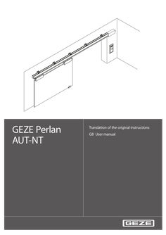
User manual Perlan AUT-NT
… User manual … Intended use The PERLAN AUT-NT sliding door drive is designed for the automatic opening and closing of the sliding leaves. The PERLAN AUT-NT sliding door drive is suitable for use in dry rooms in private areas. The PERLAN AUT-NT sliding door drive may not be used at fire or smoke protection doors and in a hazardous (Ex) area. The PERLAN AUT-NT sliding door drive may not be used to open and close vertical sliding leaves. Any other use than the proper use, such as permanent manual operation, as well as all changes to the product are impermissible. … GEZE Perlan AUT-NT Safety instructions Thoroughly read and abide by this user manual before commissioning the door. In addition, always observe the following safety precautions: àà The prescribed mounting, maintenance and repair work must be performed by properly trained personnel authorised by GEZE. àà The country-specific laws and regulations are to be observed during safety-related tests. àà GEZE shall not be liable for injuries or damage resulting from unauthorised modification of the system. àà GEZE shall not be liable if products from other manufacturers are used with GEZE equipment. àà Only original GEZE parts may be used for repair and maintenance work. àà The connection to the power supply must be made by a professional electrician. Perform the power connection in accordance with DIN VDE 0100-610. àà The electrical installation at the customer has to have an all-pole power disconnector that can be secured reliably against reactivating (e.g. lockable switch with at least … Terms Term Drive sides at 1-leaf systems Drive sides at 2-leaf systems Contactors Statement The side of the track on which the drive unit is located, is usually the closing direction of the sliding leaf The side of the track on which the drive unit is located, is usually the opening direction of the sliding leaf Button, switch or motion detector for actuating the sliding door drive. Actuation function in the "Automatic" operating mode Contactor with switch Button for opening and closing the sliding leaf. Actuation function only in the "Automatic" function operating mode. The sliding leaf is opened automatically when the button is first pressed and closed again automatically when the button is pressed the second time. The function can be activated during commissioning by parameter configuration. Push & Go If the sliding leaf is pressed manually out of the closing position during an activated Push & Go function in the "Automatic" operating mode, the sliding leaf opens automatically. Stop Self-locking switch with which immediate stopping of the sliding door drive can be triggered in case of danger. The sliding door drive remains in its current position until the user releases the stop switch again, thus terminating the stop situation. … . XX Replace the motor and/or controller if necessary. Self-test – driver fault recog- The power driver no longer outputs a fault – nition defective message Hardware – encoder fault The encoder is not connected correctly or XX Check the encoder connection. XX Replace the motor or controller. is defective XX Replace the power pack. Hardware – voltage impos- The supply voltage lies outside the perXX Replace the controller if necessible missible range sary. Memory – RAM defective A defect has been recognised in the RAM XX Replace the controller. Memory – ROM defective The programme memory has been changed or is defective Memory – EEPROM defec- The data memory is defective tive A fault state is indicated by flashing codes of the two LEDs on the controller: First the red LED flashes rapidly, then it lights up continuously for approx. 20 seconds. During these 20 seconds the green LED flashes in accordance with the fault code x times. The cycle repeats until the user resets the fault. Example: Green LED flashes
(PDF | 1 MB)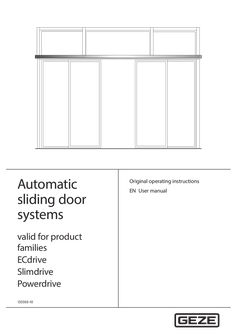
User manual Automatic sliding doors
… User manual DCU1-NT, DCU1-2M-NT, DCU1, DCU1-2M Contents … For the user … Symbols and illustrations Warning notices Warning notices are used in these instructions to warn you of personal injury and property damage. XX Always read and observe these warning notices. XX Observe all the measures that are marked with the warning symbol and warning word . Warning symbol Warning word Meaning WARNING Danger to persons. Non-compliance may result in death or serious injuries. CAUTION Danger to persons. Non-compliance can result in minor to medium injuries. Further symbols and illustrations Important information and technical notes are highlighted to explain correct operation. Symbol Meaning means “important note”; information about avoiding property damage means “additional Information” The user's attention should be drawn to important addition information. There is no danger to persons or property, but it is particularly useful to read the additional information carefully. XX Symbol for an action: This means you have to do something. XX If there are several actions to be taken, keep to the given order. Escape and rescue route; means the sliding door cannot be operated in escape and rescue routes Not an escape and rescue route; means the sliding door cannot be operated in escape and rescue routes BO … BO Break-out; means BOthat the door leaves and side panels are equipped with a break-out function BO No break-out; means the function is not possible for break-out doors Product liability In accordance with the manufacturer's liability for their products as defined in the German “Produkthaftungsgesetz” (Product Liability Act), the information contained in this user manual (product information and proper use, misuse, product performance, product maintenance, obligations to provide information and instructions) is to be noted and followed. Failure to comply releases the manufacturer from his statutory liability. … Special cases In certain cases, deviations from the information given in this user manual may occur. Examples: àà Special wiring àà Special function settings (parameters) àà Special software XX Please contact the service technician responsible for further information. … Terms Term Activation device inside (KI) Explanation Push button, switch or movement detector for activating the door drive. The activation device is located within the room enclosed by the door. Activation function in the “Automatic” and “Exit only” modes of operation. The activation device does not have any function in the “Night/Locked” and “Off” mode of operation. Activation device outside (KA) Push button, switch or movement detector for activating the door drive. The activation device is located outside the room enclosed by the door. Activation function in the “Automatic” mode of operation. The activation device does not have any function in the “Exit only”, “Night/Locked” and “Off” mode of operation. Activation device authorised Access control function (for example key switch or card reader) used by authorised (KB) persons to activate the door drive. The activation function is active in the “Automatic” “Exit only”, “Night/Locked” and “Off” modes of operation. Opening safety sensor (SIO) Presence detector (e.g. active infrared light sensor) for protecting the swinging range of the door in the opening direction. The sensor secures the secondary closing edge. Closing safety sensor (SIS) Presence detector (e.g. active infrared light sensor) for protecting the swinging range of the door in the closing direction. The sensor secures the main closing edge on the inside and outside. Emergency stop Self-locking switch with which immediate stopping of the door drive can be triggered in case of danger. The door drive remains in its current position until the user releases the emergency stop switch again, thus terminating the emergency stop situation. Emergency lock When the emergency lock is triggered, the door is closed and locked. The activations and safety devices are deactivated during the closing process. Reset Push button for restarting the drive after the operating voltage has been switched on or after a fire alarm has been terminated. When the push button is pressed, the self-retention integrated in the drive is activated, causing the drive to be activated. … For the user Fundamental safety precautions Carefully read and abide by this user manual before commissioning the door. Always observe the following safety instructions: àà Operating, maintenance and repair conditions specified by GEZE must be observed. àà The commissioning, mandatory installation, maintenance and repair work must be performed by experts authorised by GEZE. àà Any relevant additional country-specific and European directives must also be observed. àà Use in dry rooms only. àà The intervals for safety-related testing are to be complied with based on the country-specific regulations. àà The connection to the mains voltage must be made by a professional electrician. àà No changes may be made to the system without prior agreement from GEZE. àà GEZE shall assume no liability for damage caused by unauthorised changes to the system. àà The owner is responsible for safe operation of the system. àà Have a service technician check the safe operation of the system at regular intervals. àà Should safety devices be misaligned, thus preventing them from fulfilling their intended purpose, further operation is not permissible. The service technician must be informed without delay. àà Make sure that the safety stickers are attached visibly to any glass leaves and are in a legible state. àà Protect the programme switch against unauthorised access. àà Danger of injury by sharp edges on the drive when removing the cover àà Danger of injury by parts hanging down àà This appliance can be used by children aged from … years and above and persons with reduced physical, sensory or mental capabilities or lack of experience and knowledge if they have been given supervision or instruction concerning use of the appliance in a safe way and understand the hazards involved. àà Children shall not play with the appliance. àà Cleaning and user maintenance shall not be made by children without supervision. … .1 Standard functions (automatic mode of operation) In normal operation, the door is automatically opened and closed. What happens? An activation device (push button, switch or movement detector) is triggered. What does the door do? Door opens and closes again. Closing safety sensor is triggered when the door is open. Door remains open. Closing safety sensor is triggered when the door is closed. Door remains closed. Closing safety sensor is triggered while the door is closing. Door opens again. Opening safety sensor is triggered when the door is closed. Door remains closed. Opening safety sensor is triggered while door is opening. Door stops. Opening safety sensor is triggered while door is opening. The door does not stop until the reduced opening width (escape route width) has been reached. A person moves toward the opened door and a movement detector is Door remains open. activated. A person moves toward the closing door and a movement detector is Door opens again. activated. Door contacts an obstruction when opening. Door contacts an obstruction when closing. BO BO Door stops, waits and attempts to move to the open position at a reduced speed three times. Then the door closes again. Door reopens immediately, waits the hold-open time and then closes at a reduced speed. Door leaf or side panel is broken out. Door remains in the current position and can be moved manually. Door leaf or side panel is latched in again. Door functions again in the last mode of operation. BO BO 11 Description … Explanation A fault 07 (fire alarm) is displayed at the programme switch. Door closes immediately with dampened closing speed and remains closed. Changing the mode of operation is not possible. Door can only be opened manually. Normal operation is restored by pressing the reset switch. The reset switch can be reached by opening the drive cover. See Chapter 5, No mains voltage. Behaviour at smoke alarm (Slimdrive SL-RD) Operating status Smoke alarm Normal operation Mains power failure … DCU1-NT, DCU1-2M-NT, DCU1, DCU1-2M Locking/unlocking if there is no mains voltage Locking type Toothed belt locking Measures Locking only makes sense when the door is closed. Locking with drives with built-in rechargeable battery àà If the door is to be locked and this door is the only point of access: XX Push the door closed manually from the inside. XX Push the locking pin. XX Activate the (inner) authorised activation device until initialisation of the drive is completed. DPS or TPS indicates Night/Locked mode of operation. Door opens – leave the building – door closes – locks again and switches off. Unlocking from the outside with drives with built-in rechargeable battery XX Activate the (outer) authorised activation device until the drive is initialised and the door starts to open. Door opens – door closes – locks again and switches off. Unlocking from the inside with drives with built-in rechargeable battery: XX Activate the (outer) authorised activation device until the drive is initialised and the door starts to open. Door opens – door closes – locks again and switches off. Unlocking with drives without built-in rechargeable battery (only possible from the inside) XX Push the door to the desired locking position and push/slide the locking pin (9, Chapter … ). The door leaves are unlocked and can be opened manually. Rod locking, Lock A and folding door lock Locking is only possible when the door is closed. Locking with drives with built-in rechargeable battery If the door is to be locked and this door is the only point of access: XX Push the door closed manually from the inside. For sliding door with rod locking: XX Lock using an Allen key through the drill hole in the cover in the indicated direction of rotation. For sliding doors with Lock A (see also installation instructions “Automatic hook bolt lock Lock A”): Manual locking: XX Insert a tool with approx. Ø … mm at the bottom into the slot of the main closing edge/side screen profile and press the lock upwards. Manual unlocking: XX Insert a tool with approx. Ø … mm at the bottom or top of the slot in the main closing edge/side screen profile and lock in the indicated direction of movement. With folding door and folding door locking: XX Unlock with a hollow set-screw through the recess in the left post profile in the indicated direction of rotation until the door leaves can be pushed opened by hand. Locking for SL-BO Locking is only possible at a closed door. Locking with drives with built-in rechargeable battery If the door is to be locked and this door is the only point of access: XX Push the door closed manually from the inside. XX Push the locking pin. XX Activate the (inner) authorised activation device until initialisation of the drive is completed. DPS or TPS indicates Night/Locked mode of operation. Door opens – leave the building – door closes – door locks again and switches off. Unlocking from the outside with drives with built-in rechargeable battery XX Activate the (outer) authorised activation device until the drive is initialised and the door starts to open. Door opens – door closes – door locks again and switches off. Unlocking from the inside with drives with built-in rechargeable battery XX Activate the (inner) authorised activation device until initialisation of the drive is completed. Unlocking with drives without built-in rechargeable battery (only possible from the inside) XX Push the door to the desired locking position and push the locking pin (9, Chapter … ). The door leaves are unlocked and can be opened manually. After the mains voltage has been restored, the (locked) door automatically switches to the “Night/Locked” mode of operation. 19 Fault messages DCU1-NT, DCU1-2M-NT, DCU1, DCU1-2M … , Behaviour at fire alarm Door does not unlock or lock Locking defective Door does not close Closing safety sensor (SIS) interrupted or misaligned Obstruction in travel path Unlock/lock the door manually: XX Check lock in the “Night/Locked” mode of operation. If the locking is defective: XX Notify a service technician. XX Clean the closing safety sensor (SIS). XX Check settings of light curtain. XX Remove obstruction and check door leaf for ease of movement. XX Check movement detector. Movement detector triggers constantly XX Select a different mode of operation. “Hold open”, “Off” mode of operation No mains voltage (e.g. power failure) See Chapter 5, No mains voltage. Programme switch cannot be operated Programme switch is blocked Programme switch is defective Fault messages displayed Fault in the door system at programme switch Activate key switch. Enter password. XX Request servicing. See Chapter 6, Fault messages XX XX Carry out a reset/delete the fault memory àà With keypad programme switch: XX Use key or to change to the mode of operation “Off” (see Chapter
(PDF | 2 MB)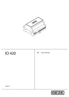
User manual IO 420
… User manual GEZE IO 420 Contents … Zu Zudiesem diesemDokument Dokument About this documentbeschreibtdie Dieses DiesesBenutzerhandbuch Benutzerhandbuchbeschreibt dieMontage, Montage,Inbetriebnahme Inbetriebnahmeund undParametrierung Parametrierungdes desGEZE GEZEIO IO420. 420. This user manual describes the installation, commissioning and parameter setting ofBenutzerhandbuchs. the GEZE IO 420. Montage und der und nicht Bestandteil dieses Montage undInbetriebnahme Inbetriebnahme derFenster Fenster undTüren Türensind sind nicht Bestandteil dieses Benutzerhandbuchs. Installation and commissioning of the windows and doors are not part of this user manual. … Product description Mit Mitdem demGEZE GEZEIO IO420 420werden werdenGEZE GEZEKomponenten Komponentenfür fürTürTür-und undFenstersysteme Fenstersystemesowie sowiedas dasRWS-System RWS-Systemvon vonGEZE GEZE With GEZE IODas 420, GEZE components for door and window systems as well as the RWS-system of GEZE are gesteuert. IO 420 zur Vernetzung der und zur nicht busfähigesteuert. Das IO 420ist istein einKoppelmodul Koppelmodul zur Vernetzung derKomponenten Komponenten und zurIntegration Integration nicht busfähi„CLOSED“. The IO 420inin isdas adas coupler module the networking of components and for the integration of non-busger GEZE Benutzerhandbuch werden die einzelnen Modultypen begerKomponenten Komponenten GEZESystem. System.Infor Indiesem diesem Benutzerhandbuch werden die einzelnen Modultypen becompliant components in the GEZEumgesetzt system. This user manual describes the individual module types that can be System werden können. schrieben, die mitdiesem diesem System umgesetzt werden können. schrieben, diemit implemented using this system. … kB (standard setting). à Instance number of “notification class object”: The IO 420 only has one “notification class object” since there is only one object for GEZE alarm messages. Parametrierung IO 420In the factory setting, multi state value #2 is allocated to this, but it can be changed by the user. The value range is between
(PDF | 3 MB)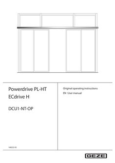
User manual Powerdrive PL-HT / ECdrive H / DCU1-NT-OP
… User manual DCU1-NT-OP Contents … General safety notices Carefully read and abide by this user manual before commissioning the door. In addition, always observe the following safety notices: àà Any relevant additional country-specific and European directives must also be observed. àà Operating, maintenance and repair conditions specified by GEZE must be observed. àà Maintenance and repair work may only be performed by properly trained personnel authorised by GEZE. àà GEZE shall assume no liability for damage caused by unauthorised changes to the system. àà Use in dry rooms only. àà The owner is responsible for safe operation of the system. Should safety devices be misaligned, thus preventing them from fulfilling their intended purpose, further operation is not permissible. Inform the service technician immediately in this case. àà In compliance with Machine Directive 2006/42/EC, a safety analysis (risk analysis) must be performed and the door system identified in compliance with CE Identification Directive 93/68/EEC before commissioning the door system. Use the "GEZE safety analysis for automatic sliding doors" here. àà The intervals for safety-related testing are to be complied with based on the country-specific regulations. … .3 Operation Special functions The special functions of the door system are triggered using special switches. Switches/push buttons What does the switch / push button do? Authorised activation device bed opening Door opens to the full opening width and closes again after the hold-open time has expired. Push button nurse opening (activation Door opens to the reduced opening width and closes again after the hold-open device KI/KA) time has expired. Cleaning opening push button (input PE1) Door opens to the full opening width and stays open. When actuated again, the door closes again. Close push button opening (input PE2) Door closes automatically. If a door is used with Push & Go without hold-open time after a manual passing and after the passing it has not closed, the doors can be closed centrally with this push button. Key switch of the programme switch If a key switch is connected to the programme switch, the operation of the programme switch can be locked or released with it Emergency shut off switch (currentless) Door opens and performs the function selected for battery operation: àà Open and switch off àà Close and switch off àà Normal operation for maximum 30 minutes or 30 open/close cycles, then open and switch off àà Normal operation for maximum 30 minutes or 30 open/close cycles, then close and switch off Door closes and remains closed Emergency stop switch … .4 Door stops and can be moved freely by hand Function changes compared to DCU1 NT / DCU1-2-NT The following functions are described in the user manual for Automatic Sliding Door Drives but are not yet available in the version DCU1-NT-OP: àà Limited hold-open setting àà Emergency lock … No mains voltage No mains voltage If the mains voltage fails (e.g. power failure), check the on-site safety fuse first. State Reaction No mains voltage (e.g. power failure) The door remains closed and then locks in "Night" operating mode. Standard drives: In the operating modes shop closing, reduced opening width, full opening width and permanently open, the behaviour of the door depends on the parameters that have been set during the initial commissioning: àà Door remains in the current position and switches off. àà With drives with built-in rechargeable battery depending on the function selected: Mains voltage available again Locking/unlocking without mains voltage active (e.g. power failure) for the toothedbelt lock àà Door closes and switches off. àà Door opens and switches off. àà Normal operation for maximum 30 minutes or 30 open/close cycles, then close and switch off. àà Normal operation for maximum 30 minutes or 30 open/close cycles, then open and switch off. The door automatically returns to the last selected operating mode. Locking only makes sense when the door is closed. Locking with drives with built-in rechargeable battery àà If the door is to be locked and this door is the only point of access: XX Push the door closed manually from the inside. XX Push the locking pin. XX Activate the inner authorised activation device until initialisation of the drive is completed. DPS or TPS indicates Night mode of operation. Door opens – leave the building – door closes – locks again and switches off. Unlocking from the outside with drives with built-in rechargeable battery XX Activate the outer authorised activation device until the drive is initialised and the door starts to open. Door opens – door closes – locks again and switches off. Unlocking from the inside with drives with built-in rechargeable battery: XX Activate the outer authorised activation device until the drive is initialised and the door starts to open. Door opens – door closes – locks again and switches off. Unlocking with drives without built-in rechargeable battery (only possible from the inside) XX Push the door to the desired locking position and push the locking pin (10, Chapter … What to do if...? Problem Door only opens and closes slowly Door opens and closes constantly Cause Floor guide area dirty Remedy XX Disconnect power supply (emergency control or on-site safety fuse). XX Clean floor guide area. XX Remove obstruction and check door leaf for ease of moveObstruction in travel path ment. Closing safety sensor (SIS) interrupt- XX Clean closing safety sensor (SIS) (light barrier). XX Check settings of light curtain. ed or misaligned Obstruction in sliding path, e.g. stone XX Disconnect power supply (emergency control or on-site safety fuse). in floor guide area XX Clear obstruction and clean floor guide area. XX Check detection field of movement detectors. Light beams or reflections, e.g. reflective floor, drops of rain, plants / flower pots, posters/displays or similar in the scanned area of the movement detector XX Check detection field of movement detectors. Misaligned movement detector Door only opens a crack Obstruction in travel path XX Door does not open Obstruction in travel path XX Movement detector misaligned or defective (inside and/or outside) Operating mode "Night", "OFF" XX Remove obstruction and check door leaf for ease of movement. Remove obstruction and check door leaf for ease of movement. Check movement detector. XX Select another operating mode. "Shop closing" operating mode XX Select "Automatic" operating mode. 14 DCU1-NT-OP Problem What to do if...? Cause Floor locks are locked Remedy XX Unlock floor locks. Lock M is locked XX Unlock hook bolt lock. No mains voltage (e.g. power failure) See Chapter 4, No mains voltage Door does not unlock or lock Door does not close Locking defective Unlock/lock the door manually: XX Check locking in the "Night" operating mode If the locking is defective: XX Notify a service technician. Closing safety sensor (SIS) interrupt- XX Clean the closing safety sensor (SIS). XX Check settings of light curtain. ed or misaligned XX Remove obstruction and check door leaf for ease of moveObstruction in travel path ment. X X Check movement detector. Movement detector triggers constantly Operating mode "Permanently open", XX Select another operating mode. "OFF" No mains voltage (e.g. power failure) See Chapter 4, No mains voltage Programme switch cannot Programme switch is blocked be operated Programme switch is defective Fault messages displayed Fault in the door system at programme switch Turn key switch. Enter password. XX Request servicing. See Chapter 5, Fault messages XX XX Carry out a reset/delete the fault memory àà TPS: XX Use key or to change to the mode of operation OFF (see Chapter
(PDF | 573 KB)
User manual MBZ 300 configuration software
… User manual Configuration Software Program for configuring RWA systems comprising components from the MBZ 300 series made by GEZE GmbH Software version … About this document About this document This user manual describes the the operation of the GEZE-MBZ 300 Configuration Software. … Symbol for a user action. Here you have to take an action. XX Observe the sequence if there are several action steps. System requirements The program can be installed on a computer with at least the following properties: CPU Operating system Memory Hard drive space Drive Graphic card / monitor Accessories Other requirements Recommended processor: … Software installation MBZ 300 Configuration Software After MBZ 300 software training you are registered in the user list. You then receive the software and licence via the GEZE customer portal. Please make sure you always work with the latest software. Please go to the GEZE customer portal: www.geze-partnerlogin.de Please install the software on a laptop which is used to commission the MBZ 300: àà You need administrator rights for installation àà Install the program in a file with writing rights for the user àà Make sure that the driver is also installed. (If this is not done automatically, the driver can be installed later from the directory „...\Programme\GEZE\MBZ300\Driver“ when an MBZ 300 control unit is installed.) … Licence levels The program can be cleared on different user levels by means of an authorisation system. Pre-condition for licensing is the acceptance of a licence contract with GEZE GmbH. … .3 Requesting licence key Please go to the GEZE customer portal as a registered software user: www.geze-partnerlogin.de There, you can enter the activation code and request the key under „Authorisation“. It can be marked using the mouse, for example, copied to the clipboard using <strg>+<c> and then pasted using <strg>+<v>. Your contact responsible will send you the suitable licence key by email as soon as possible. If you have any questions, please contact MBZ300@geze.com. … .4 General information Menu functions A wide range of different software functions can be executed via the menu in the header. Navigation is by left mouse click, analogue to familiar programs. File Load configuration... A saved configuration (*.EMB) is loaded to the software interface. It is not yet written into the system. XX Please check the settings after loading. XX The following settings are not saved in the file and must be adapted manually àà PM: àà Size of the battery àà Number of PMEs àà WM: àà Sensors àà Wind thresholds àà CM: àà Maintenance time àà Time àà Password See „System configuration“ for how to write the configuration into the system The current configuration is saved in a file (*.EMB) on the PC. Like „Save configuration...“ but under a new file name. see „Authorisation“ Protect the system by means of a password. Page set-up. Documentation of the system acceptance protocol/check list. XX Save configuration... Save configuration as ... Authorisation... Set Password of the selected device... Printer settings... Printer preview selected device... Printer preview of all devices... Print the configuration of the selected device... Print the configuration of all devices... Generate a PDF of the selected device configuration... Generate a PDF containing all device configurations... Exit Note: In order to get all current status entries in the PDF as well, click in all modules (status page) before generation / printing to ensure the current status displays are requested. Terminates the program … .5 „Buttons“ on the interface As an alternative to items from the header menu, some functions are available as buttons. The functions of the button are described below. „Clear“ The system configuration is reset to factory settings. Refer also to „System configuration“. Note: All the settings are lost! „Save to CM“ The configuration in the software interface is transmitted to the system. Refer also to „System configuration“. „Undo“ Changes to the configuration in the software interface are reversed. Note: This only affects the current view on the PC, not the control unit. For this, the configuration has to be re-transmitted to the control unit. Whether or not a property can be modified depends on the user level. 10 MBZ 300 Configuration Software … .6 General information EMU (emulator) The emulator is used to simulate system set-up when the PC is no longer connected to an MBZ 300 control unit. To simulate the system set-up, the various modules are added to a list in descending order. The modules can be moved in the list by drag-and-drop. Then the system set-up is loaded to the configuration program, where the settings can be made. PM, CM, DM, SM, DME, WM, ERM Adds the corresponding module to the list. System separation Allows a new control unit to be started in the list in order to map several control units connected via CAN-bus. (This function only becomes effective when the "Networked control units" program version is used.) Delete selection Delete all Deletes the module selected in the list Deletes all the modules from the list Load into App Def. Cfg. Loads the list as system set-up into the configuration program. When configuration has been completed it can be saved (*.EMB) in order to be exported to an actually existing control unit locally at a later date. The configuration file of an actually existing system can also be loaded into an identical, emulated system. The configuration can only be loaded to an identical control unit (same module sequence). The set-up must be known. Tip: Always save the *.PDF file in addition to the configuration file (*.EMB). XX Please check the settings on the real control unit! The following settings are not saved in the *.EMB file and must be adapted manually: àà PM: Battery size and number of PMEs àà WM: Sensors and wind thresholds àà CM: Maintenance time and time àà Password 11 General information … MBZ 300 Configuration Software Firmware update Carry out the firmware update using the „Update“ program. You will find the program in the Start menu. Please proceed as follows: XX Connect the control unit via USB XX Start Update program. Path for pre-installed software installation: START -> All programs -> GEZE -> MBZ 300 -> Update -> Update The Update program contains the following: àà Intermediate saving of the configuration àà Updating of all firmware statuses of the modules installed XX 12 àà Loading of the configuration which has been saved intermediately Starting of the software „Individual control unit“. The following settings are not saved intermediately and must be adapted manually: àà PM: Battery size and number of PMEs àà WM: Sensors and wind thresholds àà CM: Maintenance time and time àà Password MBZ 300 Configuration Software … Preparation of an individual control unit [1] Ensure the system is voltage-free (no 230V connection, no battery) [2] Insert further modules if appropriate XX [3] Check wiring between the modules àà Power supply àà Bus cable (NEVER connect or disconnect when the control unit is switched on!) àà Ensure that the cables are fitted correctly. àà Connect drives, push buttons etc. (can also be done later) àà Make sure that all line monitoring devices are connected properly XX [4] Activate the 230V supply XX [5] Connect the rechargeable battery XX [6] Keep the reset push button on the CM pressed for 20s (until all modules are flashing - not longer!). This ensures the modules are addressed correctly. This process is essential when the hardware (modules and order) has been changed. XX [7] Connect USB cable to CM and connect to the laptop. XX [8] Start the software „Individual control unit“ (please make sure you always use the current version (see „Software installation“). XX [9] Check the firmware version of the control unit to make sure it is up-to-date. XX [10] Carry out firmware update if necessary (see „Firmware update“) XX [11] Load the default settings (see „System configuration“) Standard groups (alarm / ventilation / weather groups) are formed along module settings through the selflearning function (connection of modules) or default loading. Caution: all previous settings are deleted! XX [12] Adapt battery size and number of PMEs (see „Battery settings“). XX [13] Set the individual configuration: à If new modules are added or the order is changed, the settings must be adjusted manually directly in the software. à If the hardware has not changed, you can load an already saved *.EMB-file. Prerequisite is a suitable (same) hardware configuration! Please check the settings (see Section … .4) and go to the next step. XX [14] Transmit to the control unit. XX [15] Reboot the directly connected control unit. XX [16] Check settings. XX [17] Test functions (please note interactions with GLT, BMA, relaying!). XX [18] Save central configuration as *.EMB and *.PDF and archive for the project. XX [19] In the control unit, note that the configuration has been adapted by software (user, date and rough description – print out PDF and enclose if appropriate). XX [20] Terminate software, then remove USB cable. XX XX … Control and operation of the complete system. The configuration settings of the control unit are mainly saved in the CM. Evaluation/monitoring of manual detectors. Evaluation/monitoring of automatic fire alarms or external alarm contacts. Evaluation of ventilation signals. Provision of a potential-free contact (signal relay). Connection possibility with a PC via USB Connection of several MBZ300 systems via CAN (CAN additional module necessary) Electrical properties OK ! Alarm voltage 24 V DC Input switching voltage 24 V DC Load bearing capacity signal relay 0,5 A, SELV MBZ300 USB CM Reset … .3 Emergency-close (Concerns the green push button „CLOSE/RESET“ in the connected RWA button) [•] Emergency-close [] Emergency-close and detector line reset When the emergency-close push button of the manual detector is actuated, all DMs of the smoke zone are switched to "close" and the alarm status in the control unit is reset. If a smoke detector reset should be necessary, this must be carried out directly at the module via the "RESET" push button. When the emergency-close push button of the manual detector is actuated, all DMs of the smoke zone are switched to "close" and the alarm status in the control unit is reset. The smoke detectors are also reset. „Emergency-close“ always has the effect of triggering a „CLOSE“ movement and (partly) resets the alarm status, no matter whether alarm signals (e.g. fire alarm system) are pending or not. All pending alarm signals must be removed for complete alarm reset. … line error smoke detector line 2. Common fault of the network system The system-wide issue of faults is activated. Faults are shown on all RWA buttons in the network system (all control unit modules and control units networked via CAN). Note: àà When the collective fault is activated, the LED setting „Fault“ in the CM and SM properties is set to „Alternative functions“ and the drop-down menu is deactivated. Caution: àà When the collective fault is subsequently deactivated the function of the LED must be restored manually. (see „LEDs“ in CM and SM) [] Use relay for signalling too The messaging relays of all CM and SM are switched in the event of collective fault. Note: àà Changeover contact NC/NO is inverted! àà When the relays are activated, the setting „Trigger messaging relay for:“ in CM and SM is set to „Never“ and the dropdown menu is deactivated. Caution: àà When „Use relay for signalling too“ is subsequently deactivated, the settings must be restored manually. 22 MBZ 300 Configuration Software CM - Control module àà With the MBZ 300, post cycle control means CLOSE briefly every … Purpose àà àà àà àà Evaluation/monitoring of manual detectors. Evaluation/monitoring of automatic fire alarms or external alarm contacts. Evaluation of ventilation signals. Provision of a potential-free contact (signal relay). … .3 Emergency-close (Concerns the green push button „CLOSE/RESET“ in the connected RWA button) [•] [] Emergency-close When the emergency-close push button of the manual detector is actuated, all DMs of the smoke zone are switched to „close“ and the alarm status in the control unit is reset. If a smoke detector reset should be necessary, this must be carried out directly at the module via the „RESET“ push button. Emergency-close and detector line When the emergency-close push button of the manual detector is acreset tuated, all DMs of the smoke zone are switched to „close“ and the alarm status in the control unit is reset. The smoke detectors are also reset. Note: „Emergency-close“ always has the effect of triggering a „CLOSE“ movement and (partly) resets the alarm status, no matter whether alarm signals (e.g. fire alarm system) are pending or not. All pending alarm signals must be removed for complete alarm reset. … .4 Signalling ventilation signals (venting groups) As soon as a relay module is integrated in a control unit, additional configuration possibilities appear in the venting groups. Here, the statuses of the ventilation can be assigned to the relays. „Open“, „Close“ and „Stop“ are available for each relay. If parameters are set for a relay to display Open or Close, then Open or Close is active until there is either a change in direction of movement or a „Stop“ signal is issued. The stop signal is only pending when the system is stopped manually, i.e. àà Stop by pressing the Open/Close push buttons at the same time, àà Stop by active function „Start/Stop Open/Close push button“ or àà Stop by active biased-off function 39 ERM relay module MBZ 300 Configuration Software àà Automatic switch-off by the drive is not registered as „Stop“. àà Important note: This is an indicator of ventilation signals – not window statuses! Only the vent switch signals are shown. The opening of windows by alarm or closing by alarm resetting is not shown. àà Tip: A real window position can only be mapped by end position contacts (e.g. Reed contacts). … on this SM. A manual detector-open line fault was detected on this SM. A manual detector-close line fault was detected on this SM. A smoke detector
(PDF | 6 MB)
ECturn & ECturn Inside user manual
… User handbook 196257-00 210623_GEZE_ID 196257-00_BHB-ECturn_EN.indd … . Special cases In certain cases, such as with àà Special wiring àà special function settings (parameters) àà Special software differences from the information given in this user handbook may occur. XX If this is the case, please ask the service technician responsible. … ECturn & ECturn Inside Terms Term Hinge side Explanation The side of the door where the hinges from which the door leaf is suspended are located. Usually that side of the door located in the opening direction. Opposite hinge side The side of the door facing the hinge side. Usually that side of the door located in the direction of closing movement. Contact sensors Push button, switch or movement detector for activating the drive unit. Activation function in the "Automatic" operating mode. The contact sensor does not have any function in the "Night"/"Off" operating mode. Mechanical Access control function (for example key switch or card reader) used by authorised persons to contact (KB) activate the drive. The activation function is active in the "Automatic" and "Night" operating modes. Contact sensor with Push button for opening and closing the door. Activation function only in the “Automatic” switch function mode of operation. The door is opened automatically when the button is first pressed and closed again automatically when the button is pressed the second time. The function can be activated during commissioning by parameter setting. Push & Go When the door is pressed manually out of the closing position with an activated Push & Go function in the "automatic" operating mode, the door opens automatically as soon as a specific adjustable opening angle is exceeded. Opening safety indi- Presence detector (e.g. active infrared light sensor) for protecting the swinging range of the cator (SIO) door in the opening direction. As a rule the sensor is located on the hinge side of the door on the door leaf. Closing safety indica- Presence detector (for example active infrared light sensor) for protecting the swinging range tor (SIS) of the door in the closing direction. As a rule the sensor is located on the opposite hinge side of the door leaf. Stop Self-locking switch with which immediate stopping of the drive unit can be triggered in case of danger. The drive remains in its current position until the user unlocks the stop switch again, thus terminating the stop situation. Electric strike Fail-secure electric strike Available as AC or DC electric strike version. When the drive unit is activated, the electric strike is switched on by the control unit of the drive unit provided the door is in the closing position. The electric strike remains activated until the door has left the closing position. Fail-safe electric strike DC electric strike version. The electric strike is switched off when the drive unit is activated provided the door is in the closing position. The electric strike remains switched off until the door has left the closing position. Bolt feedback The bolt feedback function is a contact integrated in the lock latch that is activated when the door is locked mechanically by the tie bolt of the door lock. It signals to the control unit that the door is locked mechanically and can therefore not be opened by the drive unit. In this case the control unit ignores the control activation of all the contact sensors. … Safety notices Safety precautions Carefully read and abide by this user handbook before commissioning the door. In addition, always observe the following safety notices: àà The mandatory installation, maintenance and repair work must be performed by properly trained personnel authorised by GEZE. àà The country-specific laws and regulations are to be observed during safety-related tests. àà GEZE is not liable for any injuries or damage whatsoever resulting from unauthorised changes to the system. àà GEZE does not accept any warranty for combinations with third-party products. àà Furthermore, only original GEZE parts may be used for repair and maintenance work. àà The connection to the mains voltage must be made by a professional electrician. The power connection and safety earth conductor test must be carried out in accordance with DIN VDE 0100-610. Exception: If the ECturn swing drive is connected to the mains voltage by the mounted power plug, the connection does not have to be carried out by a qualified electrician. àà Use an on-site 10-A automatic circuit-breaker as the line-side disconnecting device. àà Protect the programme switch against unauthorised access. àà If a battery is connected: àà Check the battery function once a month. àà Recycle defective batteries. àà If changes are carried out in the detection field of the safety indicators (e.g. objects added or removed): àà Reteach the drive. àà Observe the latest versions of directives, standards and country-specific regulations, in particular: àà BGR 232 "Guidelines for power-operated windows, doors and gates" àà EN 16005 “Power operated pedestrian doorsets – Safety in use– Requirements and test methods” àà VDE 0100; Part 600 "Erection of low-voltage installations" àà Accident-prevention regulations, especially BGV A1 "Principles of prevention" and BGV A2 "Electrical systems and equipment". àà The relevant regional building regulations must be consulted with regard to widths of rescue routes. … s, the control unit changes back to the AU mode of operation. The automated door can be activated using the switch function. Normal switch function: àà Switch contact opens the door and the door remains in the open position. àà Switch contact closes the door. Switch function with hold-open time: àà Switch contact opens the door. àà Switch contact closes the door or the door starts to close after the hold-open time. The door opens after the elbow switch on the outside of the toilet has been pressed, and closes automatically after the set hold-open time has passed. When the push button is activated inside the toilet cabin, the system is switched to the Night mode of operation, which means the outer push button no longer opens the door. At the same time, the lights indicate that the toilet is occupied. The electric strike is supplied with current, preventing manual opening of the door from outside. Activating the "inner" push button again or through manual opening from inside, the WC function (Night mode of operation) is cancelled and the drive switched back to the automatic mode of operation. The ‘occupied’ displays and lights go out. When the door is pressed manually out of the closing system with an activated Push & Go function in the Automatic mode of operation, the door opens automatically as soon as a specific adjustable opening angle is exceeded. Switch function WC control Push & Go Push To Close Contact sensor K / Hold open If the door is closed manually a few degrees while the hold-open time runs down and the Push To Close function is activated, then it closes to the closing position automatically. Depending on the set parameter, manually closing by a few degrees from the hold open position switches the mode of operation to automatic and the door closes automatically. Door opens once and closes after the hold-open time. AU mode of operation is retained. If the push button is pressed for longer than
(PDF | 1 MB)